General Infrastructure:
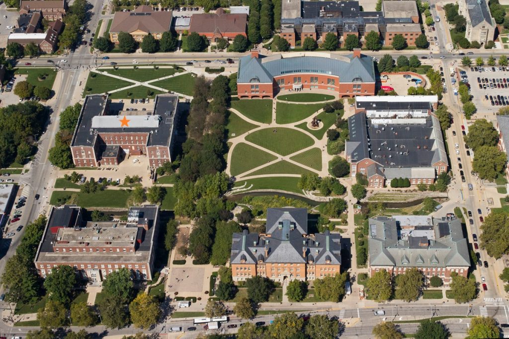
The Multiphase Thermo-fluid Dynamics Laboratory was established in 2015 and occupies 800 ft2 with 25.5 ft ceiling height in the heart of the engineering campus at the University of Illinois at Urbana-Champaign. The space includes a 3 ton overhead crane shared with the building loading bay for easy transport and installations. A 12 ft tall mezzanine and portable personnel lift provide safe and easy access to high elevations. The space is equipped with a high capacity compressed air supply, 1 MΩ four-bed water deionization system, and nearly 150 kW of available electrical power. The Laboratory also has minor machining capabilities with equipment such as a variable speed drill press and horizontal band saw. Several doors down from the Laboratory is a fully equipped and staffed machine shop for professional machining needs and consultation.
General instrumentation infrastructure includes high precision pressure transmitters; thermocouples; rotameters, magnetic, and turbine flow meters; multi-point conductivity probes; and high speed camera, lens, and lighting system. The high speed camera (Photron AX100) is capable of a maximum frame rate of 540,000 fps and full field (1024×1024) at 4,000 fps. The 20 μm x 20 μm per pixel sensor with the high magnification lens system allows for high-speed video at a magnification of nearly 3 μm per pixel. A mircro-pipet droplet system is routinely used for characterization of contact angle and surface wettability. Through strong collaborative relations within the college, access to advanced Laser Doppler Velocimetry (LDV) and Particle Image Velocimetry (PIV) is also available. Extensive microanalytical instrumentation also exists within the University of Illinois Frederick Seitz Materials Research Laboratory (FS-MRL). MRL maintains a number of instruments that can be used for material characterization at a nominal charge including AMF, AFS, XRD, SIMS, AES, XPS, TEM, SEM, FIB, and (S)TEM-EDS.
Heated Annulus Channel for Study of Phase Change Flows:
The annulus test section is scaled based on a Boiling Water Reactor (BWR) sub-channel. The configuration of the facility can be easily modified for forced convective and natural circulation flows through isolation valves. During forced convective flows the pump drives the flow through the test section and test section bypass. In this configuration the test section bypass acts to stabilize the flow in the test section. This bypass is particularly important for the stability of low pressure boiling flow which can be sensitive to inlet velocity fluctuations. Under natural circulation flow the pump section is closed off and the test section bypass becomes the feed to the test section.
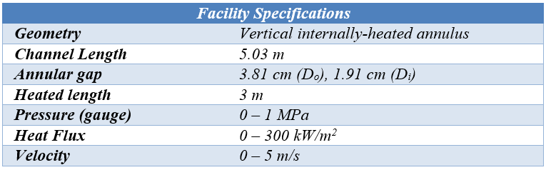
The test section forms an annulus channel with an outer pipe and inner rod with diameters of 38.1 mm and 19.1 mm respectively. This inner rod is a custom immersion heater which defines the heated region of the flow length. The facility has 3 m of heated length followed by 2 m of unheated length. Five thermocouples are embedded in the wall along the heated length for measurement of wall temperature. This test facility is capable of a wide range of system conditions such as pressure up to 1 MPa, inlet liquid velocity up to 5 m/s, and heat flux up to 300 kW/m2. The tests section is fully modular allowing for the five measurement ports, and the option for up to five custom viewports to be installed anywhere in the test section. The five measurement ports can span the entire test section for a study of boiling, condensing, and flashing flows, or concentrated in the heated or unheated region for more resolution of a particular phase change phenomenon. The measurement ports house instrumentation for pressure, and local temperature, void fraction, gas interface velocity, interfacial area concentration, and Sauter mean diameter. By traversing a four-point conductivity probe, and thermocouple, local measurements of the two-phase mixture and bulk liquid temperature can be obtained. The five viewports, with custom fabrication for a smooth inner diameter to match the test section, can also be placed at any location along the test section for detailed visualization, Laser-based measurement, and high-speed imaging. The four-point conductivity probes are fabricated in-house from electrically insulated needles allowing for minimal flow disturbance and high measurement resolution. The conductivity probe has been well established for local measurement of two-phase flow properties.
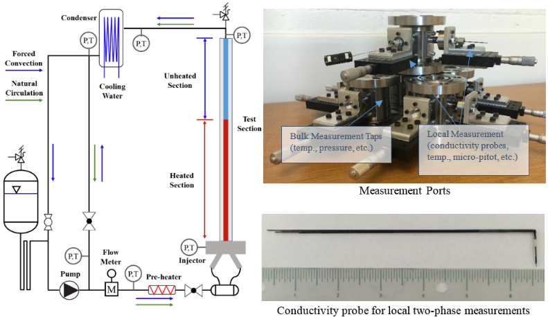
Figure 1. Existing experimental facility for measurement of phase-change flows: (left) schematic layout of the facility, the five instrumentation ports with ability to traverse instruments within the flow area (right top), and an example of in-house conductivity probe (right bottom).
Applications of the heated annulus are:
- Two-phase transport in boiling, condensing, and flashing flows
- Local measurement of void fraction, interfacial area, Sauter mean diameter, gas velocity, liquid temperature
- CFD code validation data
- System code validation data
- Natural circulation and thermal hydraulic instability
- Two-phase flow around obstructions
Video exhibiting the unique instability data observed:
Conductivity Probes
Conductivity probes are a useful tool for measuring two phase flows in channels. By measuring the voltage between the probe and the channel walls and recognizing that liquid is a better conductor than gas, we can use the probe data to study void fraction, which is the ratio of gas volume to total volume and the number of bubbles present. By combining 4 probes together, with one probe set ahead of the others, bubble size and bubble velocity can be determined by measuring the time delay in the signals. Accurately measuring these parameters allows us to better understand heat transfer in reactors.
High Heat Flux Rectangular Channel:
A closed-loop test facility, Figure 2, has been built to investigate two-phase heat transfer and critical heat flux. A pump is installed to drive the working fluid in the facility. The flow rate in the facility is measured with the option of a high or low range turbine flow meter. The facility is pressurized with compressed nitrogen through a pressurizing tank up to 1 MPa where the pressurizing tank is separated from the main system by a long stainless steel tube to prevent the entry of non-condensable gases. Precise liquid inlet temperature is controlled by the combination of the condenser, which extracts heat to secondary side cooling water, and a pre-heater located upstream of the test section operated by a PID controller. The test section bypass and globe valve upstream of the inlet provide fine control of the flow rate and dampen pressure and flow fluctuations in the test section. The combined operation of the bypass and inlet valve are important for preventing density wave instabilities, particularly under low flow conditions.
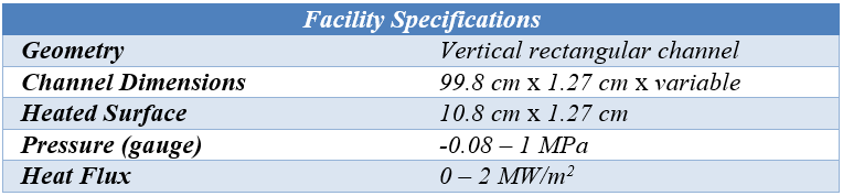
The main component of the facility is the stainless-steel test section. It has a square flow channel with dimensions of 1.27 cm × 1.27 cm × 99.80 cm. The schematic of the test section is shown in Figure 2(b). A copper heater block with seven cartridge heaters provides the heat flux through conduction to the heated surface. This surface, Figure 2 (c), is inserted into the test section approximately 32 hydraulic diameters downstream of the test section inlet to develop the flow. At the location of the heated surface, the remaining three sides of the channel house quartz viewing ports for observation of boiling dynamics. Bulk liquid temperature immediately upstream and downstream of the heated section is measured with T-type thermocouples. Pressure is also measured directly downstream of the heated surface with a high precision guage pressure transducer. The heated surface has a dimension of 12.7 mm × 107.95 mm as shown in Figure 2(c) and sets into the test section to form a continuous flow area. K-type thermocouples are embedded in the copper block to measure temperature at various locations for determination of heat flux and wall temperature. Four thermocouples are located at 1.1 mm from the surface and 6.35 mm apart from each other, while the other four are placed at 12.7 mm and 19.05 mm from the first four thermocouples. Various materials can be studied depending on the heat transfer application. Surfaces with bare copper, brazed stainless steel, brazed zircaloy-4, coated chromium, and laser-texturing are available for testing.
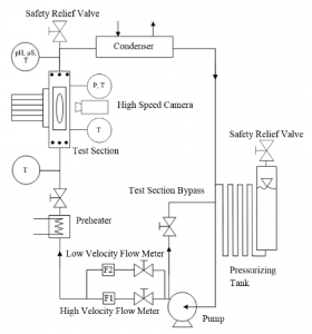
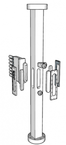
Figure 2. Existing experimental facility for measurement of boiling heat transfer and critical heat flux: (left) test facility layout and components, (right) test section with heater and view port configuration.
The facility is applied to experiments including:
- Critical heat flux measurement
- Wall nucleation measurement
- Effect of gap thickness on boiling heat transfer
- Subatmospheric boiling
- Boiling surface engineering (etching and coatings)
Stratified Pipe Blowdown Facility
In this experiment, the long pipe section is stratified with a gas space at the top such that the water-gas interface is seen at the top of the visualization port. There is also a gas space in the charging tank which is used to pressurize the system to the desired set pressure. A rapid 3-way actuated valve connected to the charging tank has a spring open mechanism to atmosphere and air actuation to the pressurization system, which can be controlled from the data acquisition system. The experiment can be performed as a blowdown experiment by opening this valve to atmosphere or as a quasi-steady oscillation experiment by cycling the valve between the atmosphere and the pressurization system.
The instrumentation is designed for validation of the seven-equation two-pressure model. Pressure transducers positioned along the test section measure the phase pressure throughout the experiment. At the viewport a highspeed camera focused on the interface, along with a laser sheet set orthogonal to the camera, measure the interface position, interface velocity and phase velocities. The highspeed camera directly measures the interface position and velocity. The gas and liquid can be seeded with small particles (such as smoke in the gas phase and florescent particles in the liquid phase) and illuminated by the light sheet to measure the phase velocity through PIV techniques. A mass flow meter is provided in the surge line for additional measurement of the test section boundary.
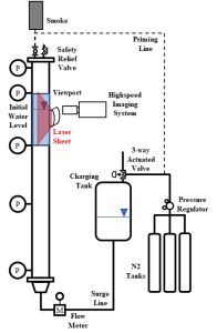
Figure 3. Schematic of stratified pipe blowdown facility.
This facility is applied to experiments including:
- Validation of data for the system under rapid transients (system and CFD codes)
- Benchmark of interfacial balance equations under rapid transients
Molten Salt Sparging and Covergas Facility
Under construction.
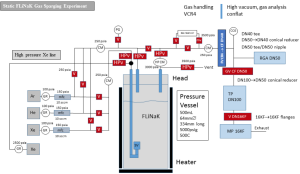
Figure 4. The layout of the facility under construction.
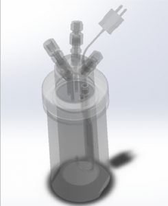
Figure 5. A CAD depiction of the vessel for the facility.
This facility is applied to experiments including:
- Solubility of gases in molten salt
- Effects of covergas on molten salt
- Effects of gas sparging on molten salt
- Material corrosion in molten salt environments
Quenching Demonstration
The purpose of the experiment is to demonstrate the phenomenon of film boiling, present real-time data and derive related variables by LabVIEW, including the change of temperature as a function of time, and boiling curve (Fig. 4). Different boiling regimes can be observed during the trails. A metal sphere is heated to around 450 oC, then submerged into water, to create saturated or subcooled boiling, depending on the temperature of water. Two thermocouples are embedded within the sphere and connected to an NI Data acquisition system, outputting the average temperature of the metal as a function of time during the experiment. High speed camera gives the opportunity of a closer look at the film boiling (see video below).
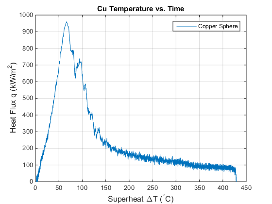
Figure 6. Boiling curve of Copper sphere with saturated water temperature.